

J-K Flip-flop And T-Flip-flop
J-K Flip-flop And T-Flip-flop both are the types of flip-flops. J-K flip-flop is basically a gated S-R flip-flop with the addition of the clock input circuit. T-flip-flop is known as toggle flip-flop.
J-K flip-flop
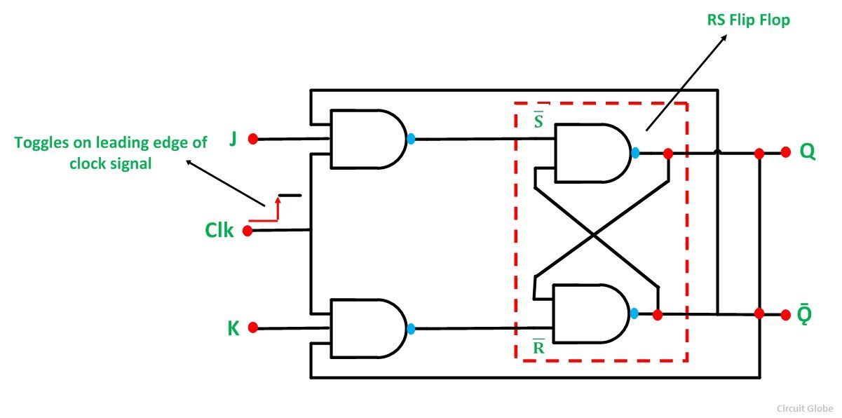
A J-K flip-flop is basically a gated S-R flip-flop with the addition of the clock input circuit. A J-K flip-flop is a refinement of S-R flip-flop in that the indeterminate states of S-R type is defined in J-K type. Input J and K behaves input S and R to set and clear the flip-flop. When the inputs are applied to both J and K simultaneously the flip-flop switches to its complement state i.e, if Q=0, it switches to Q=1, and vice-versa.
Diagram of J-K flip-flop
Truth table for J-K flip-flop
| PS(present state) | NS(next state) | ||
| J | K | Qn | Qn+1 |
| 0 | 0 | X | Qn |
| 0 | 1 | X | 0 |
| 1 | 0 | X | 1 |
| 1 | 1 | X | Ǭn -toggle |
Characteristics table for J-K flip-flop
The next state (Qn+1) is dependent on the present input J and K and the previous state.
| Qn | J | K | Qn+1 |
| 0 | 0 | 0 | Qn=0 |
| 0 | 0 | 1 | 0 |
| 0 | 1 | 0 | 1 |
| 0 | 1 | 1 | Ǭn=0=1 |
| 1 | 0 | 0 | Qn=1 |
| 1 | 0 | 1 | 0 |
| 1 | 1 | 0 | 1 |
| 1 | 1 | 1 | Ǭn=1=0 |
Excitation table for J-K flip-flop
Excitation table can be derived from the characteristics table.
| Qn | Qn+1 | J | K |
| 0 | 0 | 0 | X |
| 0 | 1 | 1 | X |
| 1 | O | X | 1 |
| 1 | 1 | X | 0 |
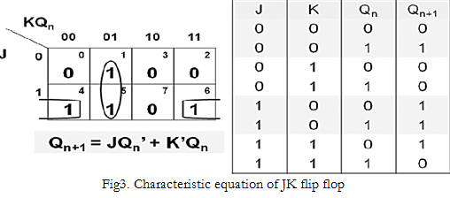
Characteristics equation for J-K flip-flop
The characteristics equation can be generated by the characteristics table using K- map
T-flip-flop
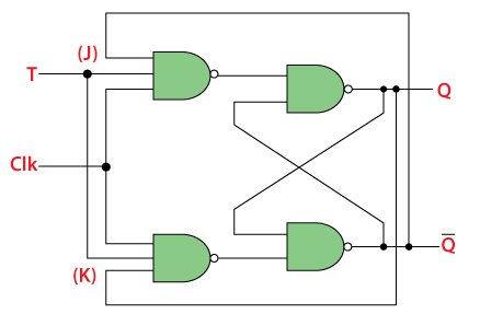
T-flip-flop is known as toggle flip-flop. The t-flip-flop is the modification of J-K flip-flop. T-flip-flop is obtained from J-K flip-flop by connecting both J and K together.
Diagram
Truth table
| T | Qn(PS) | Qn+1(NS) |
| 0 | X | Qn |
| 1 | X | Ǭn |
Characteristics table
| T | Qn | Qn+1 |
| 0 | 0 | 0 |
| 0 | 1 | 1 |
| 1 | 0 | 1 |
| 1 | 1 | 0 |
Excitation table
| Qn | Qn+1 | T |
| 0 | 0 | 0 |
| 0 | 1 | 1 |
| 1 | 0 | 1 |
| 1 | 1 | 0 |
Master-Slave J-K Flip-flop
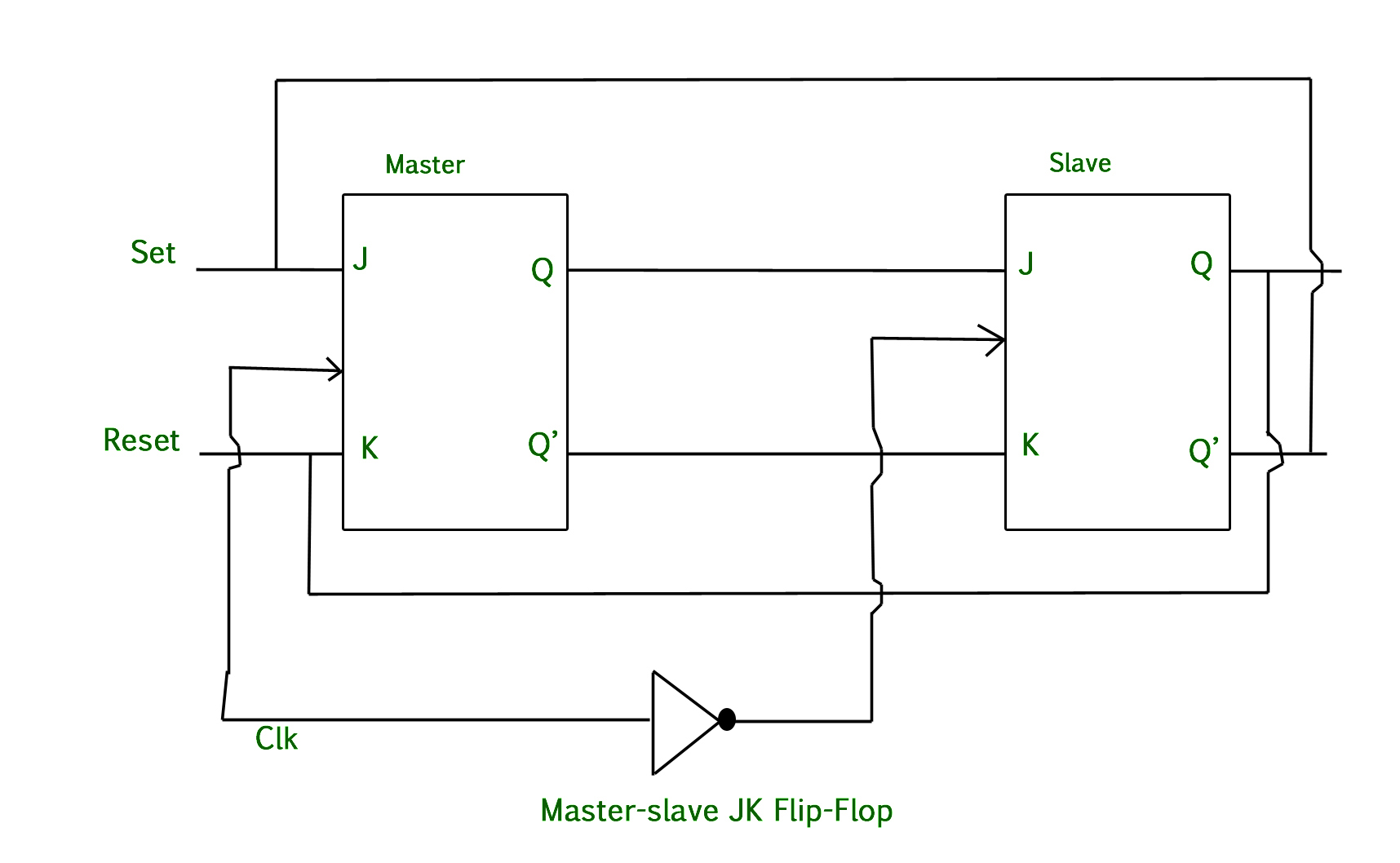
The master-slave flip-flop is basically a combination of two J-K flipflops connected together in a series configuration. out of these one-acts as a master other as slave. The output from the master flip-flop is connected to the two input of the slave flip-flop whose output is a feedback to the input of the master flip-flop.
A working condition of the master-slave flip-flop.
- When the clock plus go to one the slave is isolated J and K may affect the state of the system. The slave flip-flop is isolated unit the clock plus goes to zero. When the clock plus goes to zero information is passed from master to the slave then, the output is obtained.
- Firstly master flip-flop is a positively level trigger so the master responded before the slave.
- If J=0, K=0 the flip-flop is disabled and Q remain constant.
- When J=0 and K=1 the high Q-output of master goes to the K-input of slave the positive transection of the clock sets the slave copying the master.
- If J=1, K=0 the high Q-output of the master goes to the J-input of the slave and negative transection of the clock sets the slave copying the master.
- If J=1, K=1 toggles on the positive transection of a clock and thus slave toggle on the negative transection of clock.
Diagram
You may also likeSet(S)-Reset(R) Flipflop || Sequential Logic || Bcis Notes
I think there is something wrong on T ff’Excitation table.
Thank you for informing us and it has been updated.