

Fall 2015 Digital Systems
This is the question set along with the answers of Fall 2015 Digital Systems which was taken by the Pokhara University (PU).
POKHARA UNIVERSITY(PU)
| Level: Bachelor | Semester – Fall | Year: 2015 |
| Program: BCIS | Full Marks: 100 | |
| Course: Digital Systems | Pass Marks: 45 | |
| Time:3hrs | ||
| Candidates are required to give their answers in their own words as far as practicable. | ||
| The figures in the margin indicate full marks. | ||
Section “A”
Very Short Answer Questions
| SN | Attempt all the questions. | 10×2 |
| 1 | Convert (67)10 to Gray code. | 2 |
| 2 | State de morgan’s theorem. | 2 |
| 3 | Design 3 input NAND gate using 2 input NAND gate. | 2 |
| 4 | How many flip-flops are there in 5 bits serial out shift registers? | 2 |
| 5 | If there are 2345 inputs un multiplexer. Find number of selection lines and output lines. | 2 |
| 6 | Rechye 8:1 max using two 4:1 max. | 2 |
| 7 | Write advantages of CMOS over TIL. | 2 |
| 8 | Define fan out and fan in? | 2 |
| 9 | What do you mean by ripple counter? | 2 |
| 10 | Define one bit memory. | 2 |
Section “B”
Descriptive Answer Questions
Attempt any six questions. 6X10
11.Convert the following number from the given base to the other bases indicated.
- (1156)8 = ( )16
- (3FD.ED)16 = ()10
- (206)10 = ()5
- (1011.1011)2 = ()10
- (110011)Gray code = ( )BCD
12.Simplify the following expression using Boolean algebra.
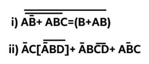
- What is Don’t care condition? Simplify the Boolean function in SOP and POS form:
F (w, x, y, z) = Σ (0, 1, 4, 6, 10, 11, 12)
D (w, x, y, z) = Σ (2, 3, 6, 9, 15)
- Explain full subtractor. Design Full Adder using two half adder and OR gate.
- Design a 3-bit binary gay code counter.
- Design a 4-bit ALU and explain its expression.
- What is full adder? Explain with help of truth table, block diagram and circuit diagram. Also construct full adder with the help of two half adders and an OR gate. Explain in details.
Section” C”
Case Study
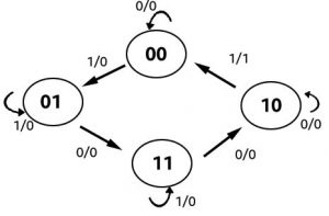
18.Draw the excitation table for RS, JK, T and D flipflop. Design a sequential machine for the state diagram shown in figure below. (20)
These are the questions by Pokhara University Fall 2015 Digital Systems.
You may also like Pokhara University || Fall 2016 Digital Systems||
Leave a Reply