

Introduction to USART
A USART (Universal Synchronous/Asynchronous Receiver/Transmitter) is a microchip that facilitates communication through a computer’s serial port using the RS-232C protocol. USART provides the computer with the interface necessary for communication with modems and other serial devices. However, unlike a UART, a USART offers the option of synchronous mode. In program-to-program communication, the synchronous mode requires that each end of an exchange respond in turn without initiating a new communication. Asynchronous operation means that a process operates independently of other processes.
Practical differences between synchronous mode (which is possible only with a USART) and asynchronous mode (which is possible with either a UART or a USART) can be outlined as follows:
- The synchronous mode requires both data and a clock. The asynchronous mode requires only data.
- In synchronous mode, the data is transmitted at a fixed rate. In asynchronous mode, the data does not have to be transmitted at a fixed rate.
- Synchronous data is normally transmitted in the form of blocks, while asynchronous data is normally transmitted one byte at a time.
- Synchronous mode allows for a higher DTR (data transfer rate) than asynchronous mode does if all other factors are held constant.
Block Diagram of 8251 USART –
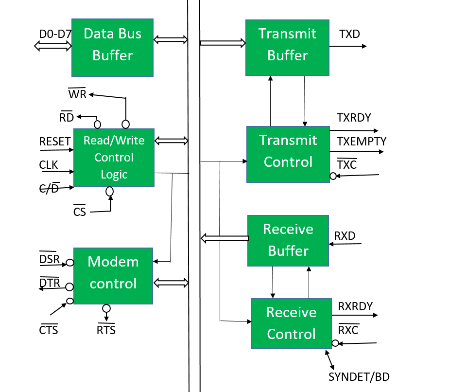
It contains the following blocks:
- Data bus buffer –
This block helps in interfacing the internal data bus of 8251 to the system data bus. The data transmission is possible between 8251 and CPU by the data bus buffer block. - Read/Write control logic –
It is a control block for the overall device. It controls the overall work by selecting the operation to be done. - Modem control (modulator/demodulator) –
A device converts analog signals to digital signals and vice-versa and helps the computers to communicate over telephone lines or cable wires. - Transmit buffer –
This block is used for parallel to serial converter that receives a parallel byte for conversion into a serial signal and further transmission onto the common channel. - Transmit control –
This block is used to control the data transmission with the help of the following pins:
- TXRDY: It means the transmitter is ready to transmit data character.
- TXEMPTY: An output signal which indicates that TXEMPTY pin has transmitted all the data characters and transmitter is empty now.
- TXC: An active-low input pin that controls the data transmission rate of transmitted data.
You may also like The 8237 DMA Controller
Leave a Reply