

Multiplexing
Muxing (or) multiplexing can be defined as; it is a way of transmitting various signals over a media or single line. A common kind of multiplexing merges a number of low-speed signals to send over an only high-speed link, or it is used to transmit a medium as well as its link with the number of devices. It provides both privacy & Efficiency. The entire process can be done using a device namely MUX or multiplexer, and the main function of this device is to unite n-input lines for generating a single output line. Thus MUX has many inputs & single output. A device is called DEMUX or demultiplexer is used at the receiving end which divides the signal into its component signals. So It has a single input and a number of outputs.
Types of Multiplexing Techniques
Multiplexing techniques are mainly used in communication, and these are classified into three types. The 3 types of multiplexing techniques include the following.
• Frequency Division Multiplexing (FDM)
• Wavelength Division Multiplexing (WDM)
• Time Division Multiplexing (TDM)
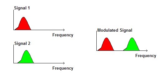
1). Frequency Division Multiplexing (FDM)
The FDM is used in telephone companies in the 20th century in long-distance connections for multiplexing the number of voice signals using a system like a coaxial cable. For small distances, low-cost cables were utilized for different systems such as bell systems, K-and N-carrier, however, they don’t let huge bandwidths. This is analog multiplexing used to unite analog signals. This type of multiplexing is useful when the link’s bandwidth is better than the United bandwidth of the transmitted signals.
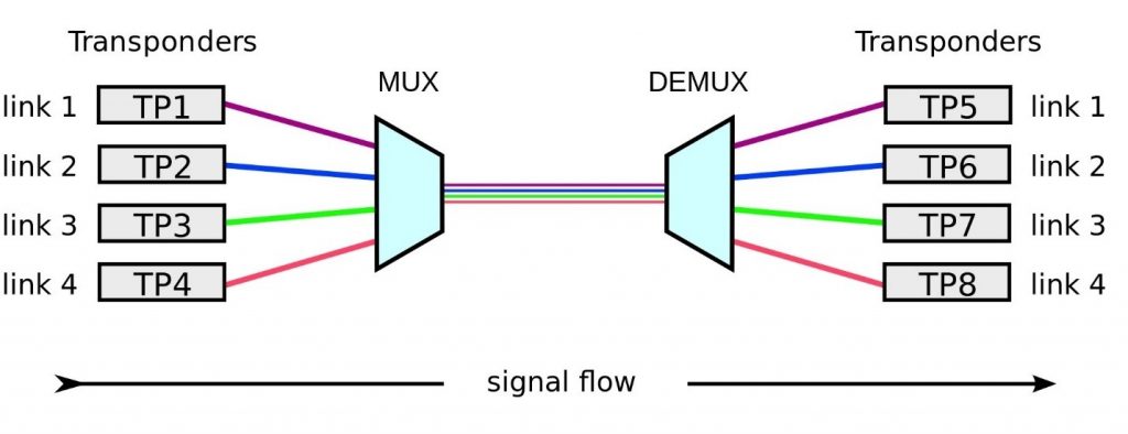
2). Wavelength Division Multiplexing (WDM)
In fiber communications, the WDM (Wavelength Division Multiplexing) is one type of technology. This is the most useful concept in high-capacity communication systems. At the end of the transmitter section, the multiplexer is used to combine the signals as well as at the end of the receiver section, de-multiplexer for dividing the signals separately. The main function of WDM at the multiplexer is for uniting various light sources into an only light source, and this light can be changed into numerous light sources at the de-multiplexer.
3). Time Division Multiplexing (TDM)
The Time-division multiplexing (or) TDM is one kind of method for transmitting a signal over a channel of particular communication with separating the time edge into slots. Like single slot is used for each message signal.
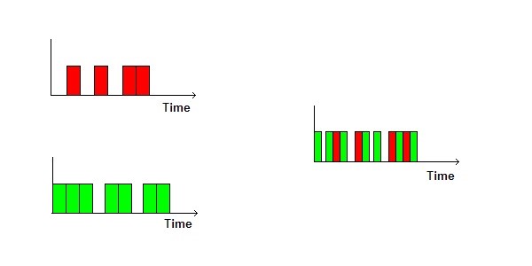
TDM is mainly useful for analog and digital signals, in which several channels with low speed are multiplexed into high-speed channels used for transmission. Depending on the time, every low-speed channel will be assigned to an exact position, wherever it works in the mode of synchronized. Both the ends of MUX and DEMUX are synchronized timely & at the same time switch toward the next channel.
Types of Time Division Multiplexing
The different types of TDM include the following.
• Synchronous TDM
• Asynchronous TDM
• Interleaving TDM
• Statistical TDM
LINE CODING
Line coding refers to the process of converting digital data into digital signals. Whenever we transmit data it is in the form of digital signals, so with the help of line coding, we can convert a sequence to bits (or encoding) into a digital signal which then again converted into bits by the receiver (or can be said as decoded by the receiver). For all this to happen we need line coding schemes which could also be able
to avoid overlapping and distortion of signals.
Some necessary characteristics of line coding schemes:
• Less complexity.
• Should have noise and interference tolerance.
• No DC component (or say low-frequency component) should be there because it can’t be transferred to larger distances.
• Least baseline wandering should be there (baseline wander: low-frequency noise having nonlinear and non-stationary nature).
• Should have error detection capability.
• Should be self-synchronized.
So in this article, we are going to talk about three types of line coding schemes:
1. Unipolar
2. Polar
3. Bipolar
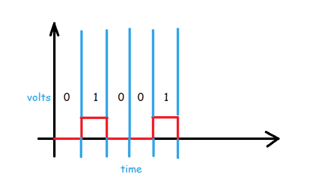
1.Unipolar Line Coding
In Unipolar we are simply representing a signal in a graphical form where positive voltage represents logical or binary 1 and zero voltage represents logical zero. We can say that it’s the simplest line code. The drawback of this scheme is that it is not self-clocking which means that it can’t be decoded without a separate clock signal or any other synchronization source. And as we discussed in the characteristics section that there should be no DC component present which it significantly contains, which can be halved by returning to zero in the middle of the bit
period.
NRZ (Non-Return to Zero):
The term Non-Return to Zero (NRZ) means that the signal (the red line in the above diagram) will not return to zero in the middle of the bit (i.e. either 0 or 1). Unipolar schemes were generally designed as NRZ schemes. But if we compare it to the polar NRZ scheme, this scheme leads to wastage of power i.e. the normalized power (i.e. the power required to send 1-bit per resistance) is almost double as compared to polar NRZ.
Because of all these reasons unipolar encoding is not normally used in data communications today.
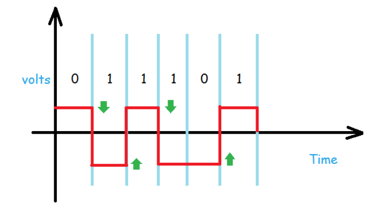
Polar Line Coding
As its name suggests polar which means it will have both positive and negative values for voltages or amplitude, it is quite like NRZ scheme but, here we have NRZ-L (i.e. NRZ-Level) and NRZ-I (i.e. NRZInvert).
Let’s see how these are represented:
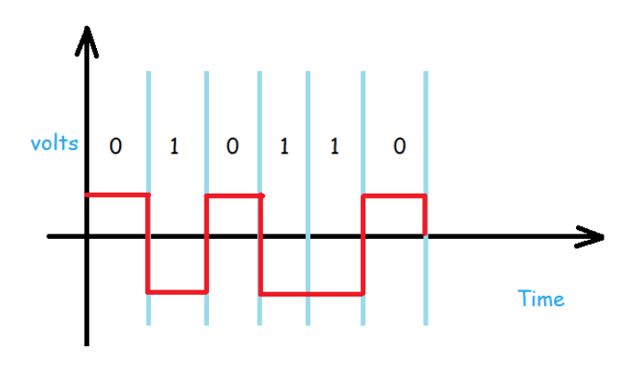
In the above diagram, we can simply notice that high volt is for logical 0 and low volt is for logical 1. This is the representation of NRZ-Level.
3.Bipolar Line Coding
Bipolar consists of three voltage levels which are positive negative and zero. While representing, the voltage level for one bit of data is at zero, and the other bit inverts of transits or alternates between positive and negative voltage.
You may also like Analog and Digital Modulation
Leave a Reply